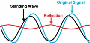
Radio Frequency (RF) Filters are special circuits that allow a signal of interest to pass through while attenuating any undesired signals. And while there are a large number of different filter topologies, there are generally 4 filter responses, or shapes, when plotted in the frequency domain. These four shapes are:
- Low Pass
- High Pass
- Band Pass
- Band Reject
Before we discuss the different filter shapes and their applications, a few terms need to be defined.
- Pass Band – The part of the filter that allows the desired signal to pass
- Insertion loss – A term that represents how much a signal is reduced when it passes through a filter
- Corner Frequency – The frequency where the filter begins the transition from low insertion loss to high insertion loss or vice versa
As the name implies low pass filters allow signals below their corner frequencies to pass through with minimum insertion loss while attenuating all of the signals above the corner frequencies. The amount of insertion loss in the pass band is dependent upon many factors such as filter topology, quality of components, layout, etc. The filter topology will also determine how quickly the filter transitions from the pass band to the achieve its ultimate rejection. Figure 1 illustrates a low pass filter plot depicting amplitude versus frequency.
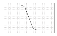 Figure 1: Typical filter shape of a Low Pass Filter.
One common application for low pass filters is the suppression of harmonics generated by an RF amplifier. This is important to prevent unwanted interference in different transmission bands. Low pass filters are also used at the output of digital to analog converters to reduce the harmonics and create a signal that is more sinusoidal.
A high pass filter serves as the inverse of a low pass filter. The low frequencies are suppressed while the high frequencies pass through with minimum attenuation. Figure 2 illustrates a high pass filter plot depicting amplitude versus frequency.
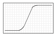 Figure 2: Typical filter shape of a High Pass Filter.
While not as common as the low pass filter, high pass filters are typically used as part of a diplexer. A diplexer allows 2 RF circuits operating at different frequencies (such as a transmitter and a receiver or 2 transmitters) to share the same antenna without interference.
A band pass filter only allows a defined band of frequencies to pass through while attenuating all of the other frequencies. Figure 3 illustrates a band pass filter plot depicting amplitude versus frequency.
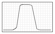 Figure 3: Typical filter shape of a Band Pass Filter.
Band pass filters are commonly used in multiple locations inside an RF system. They can mitigate the effect of co-site interference on a receiver, reduce the level of the local oscillator, intermediate frequency, and undesired mixing products at the output of a frequency mixer. Band pass filters can also be used in transmitter circuits to prevent the generation of excessive out-of-band thermal noise.
The final filter shape is the inverse of the band pass filter. The band reject, also called a notch, filter only suppresses the signals within the rejection band. Figure 4 illustrates a band reject filter plot depicting amplitude versus frequency.
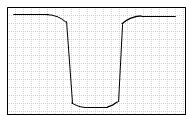 Figure 4: Typical filter shape of a Band Reject Filter.
Band reject filters are typically used to reduce a single signal that is interfering with a system. One important use is in transmitter systems that are collocated with Global Positioning System (GPS) antennas. A band reject filter can reduce the broadband noise of the transmitter at the GPS frequencies so that the transmitter does not unintentionally override the GPS signal.
Check out how our RF filter design services can boost your RF project, and don’t forget to check out our products site to view our line of COTS filters and quick turn filters that can help with all of your RF filtering needs!

