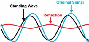
Virtually all disciplines apply certain inherited tricks-of-the-trade to expedite tasks. RF engineers and technicians are no different from anyone else…in that respect at least. Oftentimes there is a need for a quick and easy-to-build simple notch filter to improve laboratory measurements. For instance, an RF signal generator’s second harmonic can negatively impact measurements taken of the second harmonic of the unit under test (UUT), such as an RF upconverter, downconverter, etc.
How can one mitigate this? One approach is to insert a tunable notch filter into the mix to reduce the effects of the signal generator’s second harmonic. However, tunable notch filters may not always be readily available in the lab. RF technicians have developed an alternative to using a commercial tunable notch filter by using common lab supplies to create their own notch filters. Here is what’s needed:
1. Network Analyzer
2. Pair of 50 ohm SMA coax cables
3. SMA bullet adapter
4. SMA Tee adapter
5. SMA pigtail or one-ended cable (semi rigid coax will result in a filter less sensitive to handling)
Ideally one would cut the one-ended coax cable to a length greater than one-quarter wavelength of the desired notch frequency. If the frequency is in the microwave region however, the SMA Tee adapter and SMA bullet together are likely to be longer than a one-quarter wavelength – completely leaving the one-ended coax cable out of the equation. In this case a multiple of the desired notch frequency can be used, so start with a one-ended coax cable of at least one inch long, thus leaving plenty of length from which to cut during the tuning process.
First, offset the coaxial cables for S21 (insertion loss) by measuring on a Network Analyzer (NetAn). Next, insert the SMA Tee, with the one-ended coax cable attached (pictured), in between two test cables connected to the NetAn. The one-ended coax cable will create notches at odd multiples of the one-quarter wavelength frequency (i.e., 3x, 5x, etc.). [Note that had the cable been shorted out rather than left open, the notches would appear at even multiples of the frequency.] At this point one can focus on the notch closest to the desired frequency but the key is it must be present lower than the desired frequency for tunability.
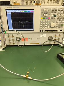
In this particular example, the center frequency of the notch prior to adjustment is 1.073369 GHz with over 36 dB of rejection.
Next, carefully snip off a small bit of the one-ended coax cable to bring the notch frequency higher. In the following picture we snipped off approximately 1/8” portion of cable.
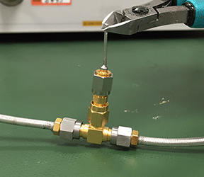 As shown by the original marker placement, the notch has now moved up higher in frequency by removal of a small section of the one-ended coax cable:
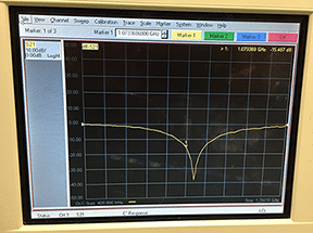 By adjusting the marker of the NetAn, one can see that this simple notch is now providing nearly 38 dB of rejection at 1.33678 GHz:
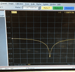
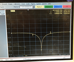
Further measurements of the notch can determine the 3 dB bandwidth of the filter, in this case 805 MHz:
 Need assistance with your communications, electronic warfare, or telemetry system design? NuWaves Engineering has an experienced technical staff with advanced RF and microwave design expertise as well as the necessary tools, facilities, and equipment to transition your ideas to hardware. Learn more.

