In the world of wireless communication, the airwaves are continually getting more and more crowded. The need for filtering signals has always existed. The need for more precise and tighter spec’d filters is increasing. More stringent demands often come with a higher price tag due to difficulties in producibility. Tighter specs mean tighter dimensional requirements, more precision while tuning, and no room for error. All of these factors drive up cost and time. If we can save time by focusing on our tuning methods, we can lower costs and drive down lead times.
Tuning a filter has been described as an “art” or requiring extensive experience to “get the feel of it”. While there is some validity in those descriptions, there are proven methods and techniques that can be employed to streamline and standardize the tuning process so that even an inexperienced technician can bring a filter into alignment quickly and efficiently.
Automated processes have been developed with the use of robotic and machine learning technologies, but these are limited to filter specific algorithms and must be changed to meet each new design. They present a good solution for long term production, but are costly to create and are not effective as a quick-turn process. In addition, there are many situations where automated tuning processes fail as the computer running its algorithm may be caught in a “loop” where all progress is halted, requiring a human to finish tuning the filter manually. This, coupled with the increasing complexity and tolerance requirements, make automated tuning processes very much an application and filter specific tool.
Traditionally, methods for tuning a filter take place in the Frequency Domain. The technician can view the insertion and return loss on their equipment; tuning each resonator and bringing the filter in for a good response. But when a misalignment occurs while setting the resonators, it can be difficult to pinpoint the exact location of the misalignment. Which resonator or resonators is out of alignment is unknown, or which resonators may be over or under coupled is unknown. Experience is a great tool, but as filters increase in complexity with more and more poles this process can take additional precious time.
Time is often thought of as the “enemy”, as we are always working against the clock to meet a demanding schedule. But, the solution to solving the problem of tuning ever increasingly complex filter designs might just be time. Time Domain. Time domain, as defined by Keysight, “refers to analysis or display, as defined by an X-Y graph where the X-axis is either distance (electrical length) or time and the Y-axis is magnitude (typically impedance or voltage).” The Time Domain option gives the technician the ability to measure impedance values along a transmission line to find discontinuities in time or distance.
In terms of tuning filters, we have the ability to “see into” the filter and map each resonator and coupling between each resonator. This gives the technician an advantage; being able to pinpoint exact which resonator may be out of alignment or where the filter may be over or under coupled.
On its own, the Time Domain function in your VNA would be mostly useless to tune a filter, but with the assistance of your design simulation data it is possible to map your real filter over your simulation data to match the response.
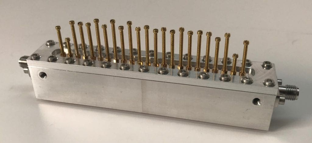
As an example, we will be tuning a difficult 12-Pole Filter centered at 2050 MHz with a bandwidth of 700 MHz. This filter is a good choice to show the effectiveness of Time Domain tuning. With 12-Poles and 11 coupling points, that gives us a total of 23 separate nodes in which to tune. First, I will start with my simulation data and load that into my Network Analyzer.
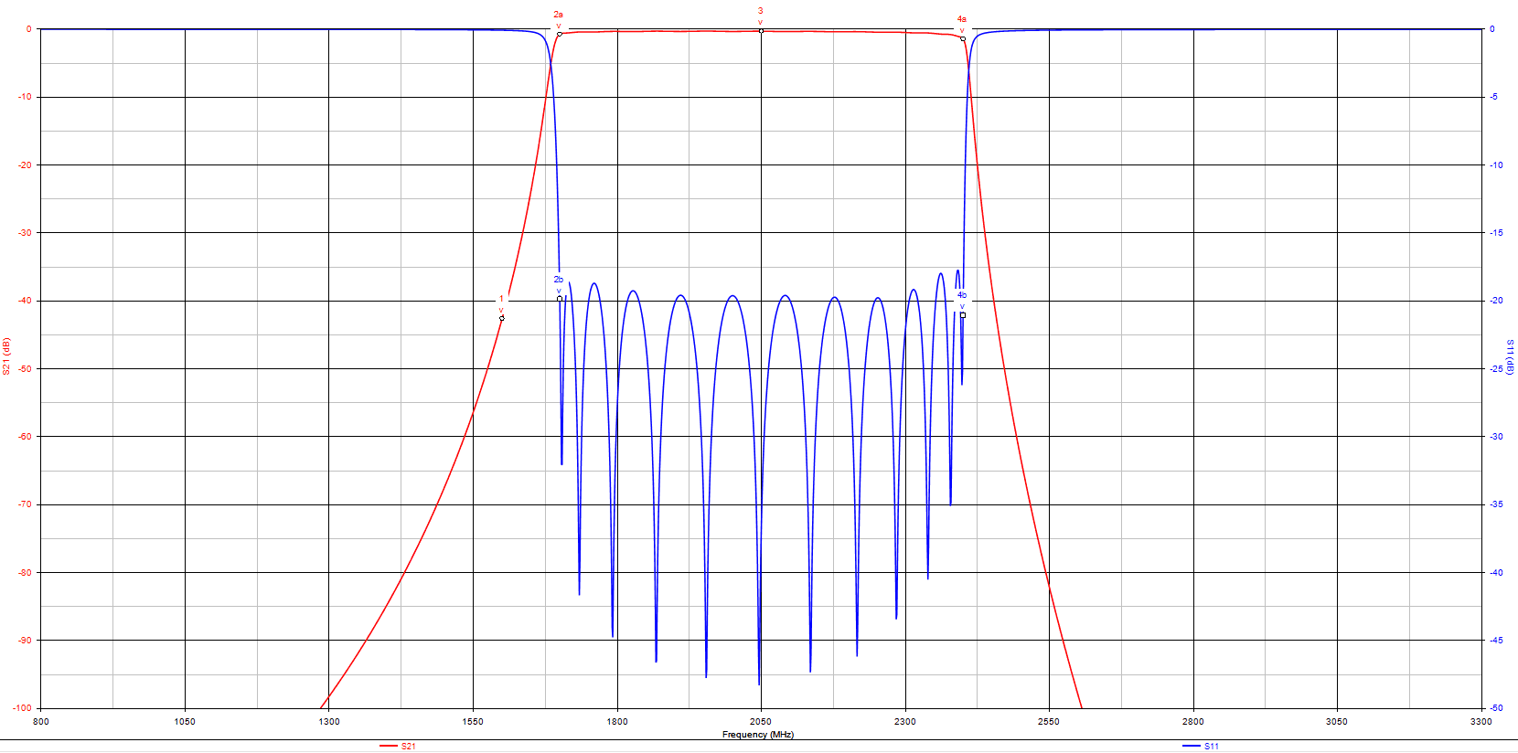
After setting up my simulation data and calibrating my Network Analyzer, I can now transform the return loss at both ports into Time Domain. This view allows one to see representations of the time response of each resonator and the coupling between each resonator in a graphical format.
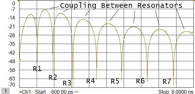
This same transformation should be done to both ports, giving you the ability to see all the poles. S11, in our example, allows us to see Resonators 1 through 7 and S22 would allow us to see Resonators 12 through 6. At this point we can overlay a second channel on the network analyzer with the continuous sweep of our real filter and begin to bring each resonator in starting with 1 and 12, then going to 2 and 11, and so forth.
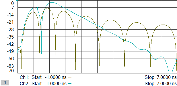
As you bring in each resonator you will notice that they push and pull on the previous and proceeding resonators, and the coupling node between them. By simply matching the real filter to the simulation in Time Domain, one can easily bring the filter up into the desired response. While an experienced technician may have an advantage, this method will allow inexperienced technicians a clear representation of which pole or coupling point may be off. A major advantage here, for more complex filters, is the ability to see exactly where the filter is detuned rather than guessing.
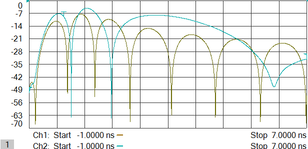
As you progress through the resonators and adjusting coupling nodes between them, you can clearly see the filter begin to take shape. The closer you can match each resonator null and coupling ridge, the closer your filter will be to the simulation. In a short amount of time the filter will be mostly tuned.
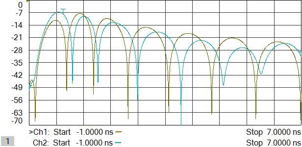
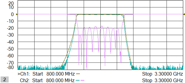
As with most theoretical designs, a simulation will not always match real world response completely, but it does give us an efficient and quick starting point that takes most of the guess work and experience out of tuning a filter. This example only needs slight tweaking to be completed and was brought to this point in far less time thanks to using Time Domain.
The example used in this demonstration is a very difficult filter to tune. With less complexity in the filter design, the efficiency of using Time Domain to tune will rise significantly.
In conclusion, the use of Time Domain can be a great time saver and useful tool uniquely suited for tuning increasingly complex filters. With the ability to “see through” the frequency response and address individual pieces of the filter, the process to tune becomes more efficient, cost effective, and precise.
_______________________________________________
NuWaves RF Solutions team designs, manufactures, and supplies a number of custom and commercial-off-the-shelf RF filters. Contact NuWaves today to see how we could engineer a long lasting partnership with you.

