The Tesla coil provides a high voltage demonstration of a resonant transformer. Although primarily used for entertainment purposes, with its long electrical arcs and noise, it also provides a path to understanding basic RF resonant circuits; just part of the many considerations involved when designing RF circuits.
Overview of Design
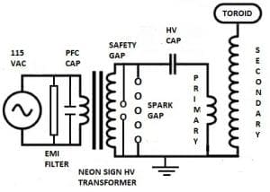
There are many paths one can take when designing a Tesla coil. For the purpose of clarity, I will primarily be referencing a coil of my own that I consider to be a simple, small to medium sized coil. Referencing the schematic below, the coil is powered off 115vac through an EMI filter, power correction capacitor, and into the primary of a neon sign transformer (NST). The secondary of the NST outputs 7500vac into the safety gap and into the tank circuit. The tank circuit consist of a spark gap, HV capacitor, and primary coil. The primary is loosely coupled to the secondary. The toroid at the top of the secondary is where the discharge occurs.
Specifications
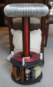
- Transformer = 7500vac @ 113ma.
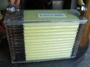
- HV Capacitor = 0.13uf @ 9kv.
- Toroid = 13” x 3” = 15pf.
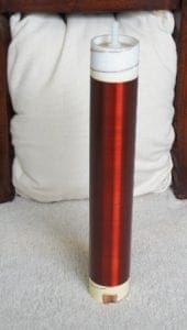
- Secondary = 12.25” x 2.38”.920turns of 30g.
- Resonant frequency = 750KHz.
- Resonant frequency w/toroid = 380KHz.
- Electrical characteristics = 9mh and 5pf.
- Primary = 8.5 turns, 13.5uh.
- Total height = 23.5”
- Base = 8.5” H x 10.5” W.
- Weight = 23lb.
EMI Filter
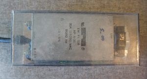
This device filters out high voltage spikes and other electrical noise that the coil may generate. This provides protection for other devices in your home or work. Of note, it’s easy to destroy a cheap EMI filter when used on a Tesla coil. The one pictured below is heavy-duty and has not caused me any problems.
Power Factor Correction (PFC) Capacitor
Technically, this device is not necessary on smaller Tesla coils as you do not draw enough current to trip a fifteen-amp circuit breaker, but I usually use one anyway. Why use a PFC capacitor? Because the NST is a large inductor, it will cause a phase shift between the incoming voltage and current (the current lags the voltage.) By adding a specified amount of capacitance across the transformer you can bring this phase shift back into alignment. You may draw 9A from the line without a PFC capacitor installed, and 6A with one installed. I did not use a PFC here but rather a motor start capacitor. Generally, this is not recommended, but since PFC capacitors are comparatively large and expensive, I gave the motor start capacitors a try. I bought a box of used motor start capacitors many years ago for a couple dollars each. Voltage wise they are overrated by a good margin, and since I usually do not run my coils for more than ten minutes, there is no risk of overheating these capacitors.

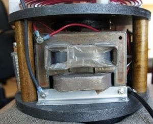
Power Transformer
I use neon sign transformers. There are other transformers that can be used but all have their own issues. Neon sign transformers are current limited and provide enough power to drive most small and medium sized Tesla coils. They are cheap, or even free, if found used. With effort, they can be made more reliable, and the current can be increased. This is accomplished by un-potting the transformer. They come potted in an asphalt or tar like substance that I have found causes more failures than the transformer itself. By removing the potting material, the metal housing, and electrodes, you can shed at least a third of the transformer’s weight. Another big plus to unpotting is that you gain access to the magnetic shunts that limit the current. I typically only unpot larger current transformer in the 60ma range. Some shunts can be removed to easily allow 100ma of current, a nice power boast.
There are other transformers such as a pole transformer, that have high power but need external current limiting. They are heavy, full of oil, and lethal. These are necessary for very large Tesla coils. Oil furnace ignition transformers are small and low power (10ma). Microwave oven transformers are small but can provide a lot of power. These are usually used in series to produce a satisfactory voltage level. They also need external current limiting.
Tank Circuit
This circuit consist of the HV capacitor, primary coil and spark gap. The HV capacitor and primary coil act as a resonator. The primary coil is tunable to match the resonance frequency of the secondary coil and top load combination. The spark gap acts as a switch that, when open, allows the charging of the HV capacitor and, when shorted, allows the HV capacitor and primary to resonate.
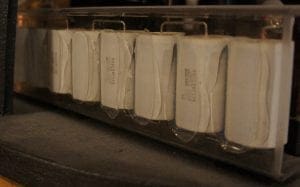
HV Capacitor
It is important to select an HV capacitor rated for pulse work with low loss, low inductance, and high DV/dt. I use Cornell Dubilier P/N 942C20P15K, these have the added advantage of being self-healing. I have also used capacitors salvaged from pulse forming networks used in old Bendix radars.
Primary
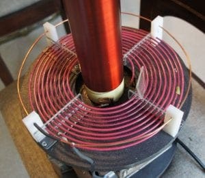
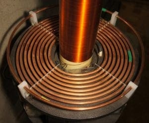
It carries a lot of current, so it is important to use heavy gage wire or ¼” copper tubing when forming it. 12g works fine for small coils and makes for a more compact coil then ¼” tubing. On the other hand, ¼” Tubing provides more surface area, and therefore less loss due to skin effect. It also looks great. The primary coil is where the tuning is performed. Tuning is accomplished by changing the tap point on the primary coil. I use the outer winding as the tunable tap and ground the inside winding.
Spark Gap
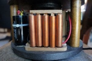
The spark gap is the switch in the system. When open, it allows the charging of the HV capacitor, when closed it allows the HV capacitor and primary to resonate. The simplest are static gaps. Most have a fan to remove the ionized gases from the gap to promote quenching and to cool the gap. Rotary gaps can significantly increase the performance of a Tesla coil. Rotary gaps control the quenching much more effectively than a static gap. Quenching is necessary to interrupt the arc at the correct time to start the cycle over. I use static gaps on my coils. They are simpler and far less costly. I always add a shrouded fan.
Safety Gap
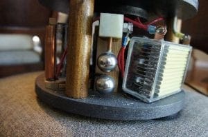
Used to protect the neon transformer from high voltage spikes in the event the static gap does not fire.
Secondary Coil
This coil, along with a top load, resonate at the same frequency as the primary and HV cap. It is important that these two resonant circuits operate at the same frequency or there will be little output.
Top Load or Terminal
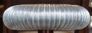
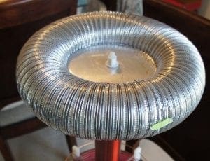
Although the terminal bolt at the top of the secondary can be used as the discharge point, the Tesla coil will perform much better if it has a sphere or toroid mounted on top of the secondary. This will add capacitance to the secondary that will drop your resonance frequency by almost 50%. It provides a surface that is more difficult to start an arc from, resulting in much higher voltages and currents being produced. I made this one using 3” flexible aluminum dryer duct welded to an aluminum center disc using Aluminum repair rod.
Coupling
Proper coupling between the primary circuit and secondary circuits is imported. Too tight and you could have arcing between the primary and secondary and/or arcing down the secondary coil. It can also make quenching the spark gap more difficult. Too little coupling and the output will be low.
Images
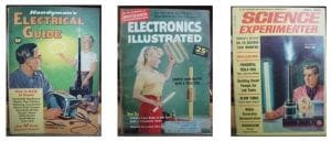
The author’s Tesla coil and some vintage magazine covers featuring Tesla coils.

Links
http://hotstreamer.deanostoybox.com/greg/frames.htm
https://www.stevehv.4hv.org/SSTCindex.htm
http://www.laushaus.com/tesla/
http://www.tb3.com/tesla/index.html
http://www.richieburnett.co.uk/tesla.shtml
______________________________________________________________________________________________
Disclaimer: All information posted was created for entertainment and educational purposes. If you act upon any information contained in the article above, you do so at your own risk.

