There are many small features which may be worth including in an RF circuit/CCA (Circuit Card Assembly).These are not important to the function of the design, but instead improve the speed and efficiency of the engineering, characterization, and test processes. In the spirit of positive business results, these additions must be simple to include in the design and construction. They also must have negligible impact on volume or weight, and involve adding only inexpensive components or features. All should be transparent to the performance of the device.
Following is a short list of examples of added features which streamline the bench work phase of the engineering and test process.
Zero-Ohm Resistors or Wire Jumpers
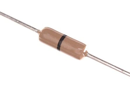
Amplifiers and other active components often have choke inductors through which VCC is applied. If there is no choke, or the choke is not possible to remove, a wire or zero-ohm jumper (which can be removed) should be included in series with the power supply to serve as a power switch. Performing engineering work on a device with an expensive high-power FET which cannot be powered down while working in another area of the CCA may result in overheating or oscillation. This may lead to wasteful component failure. The jumper also provides a cleaner, faster means of supplying externally wired power discreetly to a device for bench work.

Figure 1 Ohm axial resistor
Turn Capacitors or High Impedance Taps
Measurements may be required at certain points, or between two points, in a circuit. This can be part of the tuning, validation test, or troubleshooting process. “Tomb-stoning” or standing up series Surface Mount Technology (SMT) parts to provide a soldered coaxial test cable connection takes time, risks damage, and may not accommodate nearby ground plane for the cable stub. One way to save time and prevent damage is to include “turn capacitors” at the points in the circuit which will require external connections. This is usually accomplished by utilizing a coupling capacitor which already exists in the design. An alternate solder pad is located adjacent to the coupling capacitor footprint in the layout. The capacitor can now be turned ninety degrees and soldered to the alternate pad which is intended for test-cable attachment. Alternately, a tap resistor electrically parallel to a node in the circuit can be incorporated into the design. A 1k ohm resistor would result in a 20:1 ratio on a 50 ohm signal line. This high ratio allows the tap to be probed with little effect on the circuit during operation.
Test Point Connectors
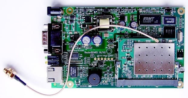
There are many surface-mount snap type coaxial connectors which can be added to the CCA design. These provide an alternative to soldering test cables to the circuit board. These snap on connectors can be mounted in series with the signal path to serve as a measurement connection. There are a variety of these connectors which also open (disconnect) the signal path to the next stage when used.

Figure 3 Embedded RouterBoard 112 with U.FL-RSMA pigtail and R52 miniPCI Wi-Fi card
Through-Hole Pulls
Some CCAs may need to be mounted and removed from a tightly fitting chassis frequently in the assembly, engineering, and test processes. Adding small through-holes in the corners of the CCA allow a small hook to be used as a removal tool versus risking damage due to using surface mount components as handles.
Load Resistor Footprints at Input and Output of Amplifier Devices
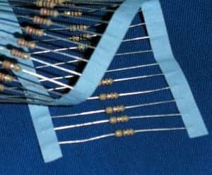
Powered active devices which are disconnected from the signal path typically require a resistive load on input and output (commonly 50 ohms) to remain stable. If this operation may be performed repeatedly during engineering work, it will be beneficial to have footprints for the load resistors in the layout.

Figure 4 Through-hole (leaded) resistors
Test Headers
Header connectors will expedite oscilloscope connection for engineering work which involves frequent monitoring of digital control or switch lines. Including test headers in the design may be more economical than constantly soldering and removing wire leads.
There are many more examples of added electronic design features which may make hardware level engineering, production and test more accurate, economical, and efficient. It should be discussed in design review which types of these features may benefit a project.
Image Attributions
-Figure 1: oomlout, CC BY-SA 2.0 <https://creativecommons.org/licenses/by-sa/2.0>, via Wikimedia Commons
-Figure 3: Kozuch, CC BY-SA 4.0 <https://creativecommons.org/licenses/by-sa/4.0>, via Wikimedia Commons
-Figure 4: The original uploader was Cyp at English Wikipedia., CC BY-SA 3.0 <http://creativecommons.org/licenses/by-sa/3.0/>, via Wikimedia Commons
About NuWaves
NuWaves RF Solutions is a premier supplier of RF and Microwave solutions for Department of Defense (DoD), government, and industrial customers. An RF engineering powerhouse, NuWaves offers a broad range of design and engineering services related to the development and sustainment of key communications, telemetry and electronic warfare systems, as well as a complete line of commercially available RF products. NuWaves’ products include wideband frequency converters, high-efficiency and miniature solid-state power amplifiers and bidirectional amplifiers, high intercept low noise amplifiers and miniature RF filters. NuWaves RF Solutions…Trusted RF Solutions™.


