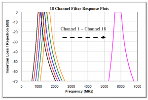
A Switched Filter Bank is a device that combines switches and filters to provide user-selectable frequency channels. Switched filter banks are beneficial to Radio Frequency (RF) communication systems and are utilized in both receivers and transmitters to reduce signal interference from harmonics, spurious emissions, strong signal interferers, and to limit noise power for optimized system performance. An input switch prior to the filter bank and an output switch after the filter bank provide a common RF signal path at the input and output of the device. A Single-Pole, N-Throw (SPNT) input and output switch is used to switch between each channel where N is the number of channels. Frequency channels are user selectable through integrated switch control and driver circuits. The frequency response of an 18 channel switched filter bank covering 1 GHz to 6 GHz is shown in Figure 1.

Figure 1: Minimum insertion loss and maximum rejection are achieved using cavity filters for the high power switched filter bank.
Switched filter banks are used in receiver RF front ends and intermediate stages where low power RF circuits and components can be utilized to perform the switching and filtering functions. These circuits and devices are more easily designed without the requirement to handle high RF power. When operating in the tens to hundreds of watts, high power switched filter banks must rely on advanced techniques to minimize insertion loss, manage thermal loads from RF power, survive high voltage conditions from VSWR mismatches, deliver high out-of-band rejection, and provide fast switching times. A fast switching speed between RF ON/OFF and RF OFF/ON supports systems with high data rates. The faster the system can switch, the quicker the data can be transmitted and received. A switching speed of ≤ 5 µs is suitable for passing high data rate signals for complex digital modulations such as OFDM based waveforms. Additionally, fast channel to channel switching speeds support frequency hopping systems, by allowing for the change between frequency to occur at a quicker rate. Fast channel to channel switching speeds are more difficult to achieve when operating at high output powers. High power RF switches and filters may not be readily available off the shelf. Especially when more than 2 RF channels are required; custom designs are often necessary to meet the switching and filtering requirements.

Figure 2: A 16 channel switched filter bank provides 16 different filter selections to minimize signal interference from harmonics, spurious emissions, and noise power.
A high power switched filter bank provides a way to easily switch between frequency channels on-the-go as the electromagnetic environment changes. The switched filter bank allows the user to quickly react and select the appropriate frequency channel to prevent signal interference while also reducing the down time of the RF link. Communications systems are increasingly expanding into other markets and hence, increasing the requirement to prevent unintentional interference between systems. Beyond satisfying regulatory requirements defined by military standards and the FCC, interference issues such as co-site interference and strong signal interferers are still common disruptors to operational success. Incorporating proper filtering to reduce harmonics, spurious emissions, strong signal interferers, and noise power, a high power switched filter bank at the output of a transmitter provides a solution to prevent the transmitter from interfering with other systems.
Switched filter banks provide:
- Improved harmonic rejection
- Rejection of spurious emissions
- Prevention of strong out-of-band interferers
- Reduction of out-of-band noise power
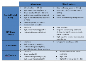
There are several options available when designing a switched filter bank. Coaxial switch relays offer broadband, high power, and low loss solutions while providing a high number of switch paths, and are readily available as Commercial Off-the-Shelf (COTS) components. Switch matrices comprised of PIN diodes, GaAs, and GaN switches offer faster switching speeds and longer operating life than relays but require greater design effort to realize a solution. A comparison of the tradeoffs of each switch technique is summarized in Table 1.

Table 1: Switch Technique Tradeoff Comparison
For more information on switched filter banks or to request a quote on a custom solution for your application, contact NuWaves Engineering.
———————————————————————————————————————
NuWaves RF Solutions is a premier supplier of RF and Microwave solutions for Department of Defense (DoD), government, and industrial customers. An RF engineering powerhouse, NuWaves offers a broad range of design and engineering services related to the development and sustainment of key communications, telemetry, and electronic warfare systems, as well as a complete line of commercially available RF products. NuWaves’ products include wideband frequency converters, high-efficiency, and miniature solid-state power amplifiers and bidirectional amplifiers, high intercept low noise amplifiers and miniature RF filters. NuWaves RF Solutions…Trusted RF Solutions™.


