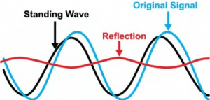
A common concern for radio frequency design engineers is providing sufficient margin in a module or system to survive the real-world application in which their work will eventually operate. Our engineering team is constantly dealing with the trade-offs of meeting the myriad of customer specifications while ensuring that our designs are robust enough to survive the unpredictable reality of fielding those designs. For instance, it is one thing to design an amplifier that operates in the perfectly controlled environment of a laboratory, but then connect that amplifier to an antenna which looks like a nice comfortable perch to a bird and you have a completely different story. One of the measuring sticks that engineers utilize to judge a system or modules robustness is to test is ability to survive a mis-matched load. Voltage Standing Wave Ratio (VSWR) is the most common method for quantifying the ability of a 50-ohm matched module to withstand the mis-matches that we all know it will experience when it is eventually fielded, with an output VSWR rating of 10:1 being common in the industry. But wait, where did that 50-ohms starting point come from?
As it turns out, there are some very practical reasons for 50-ohms becoming the standard in the RF world. Before World War II it was common to find systems matched for their specific applications. A system designed to maximize power handling might utilize an impedance of somewhere around 30-ohms, while a system seeking the lowest possible attenuation might be designed around an impedance of 90-ohms or greater. The drive to increase the pace of development and inter-operability of microwave systems leading up to and during World War II forced the industry to settle on a standard impedance for the sake of simplicity. Many of the early cables used in systems consisted of rigid copper water pipes adapted to the microwave world and utilized air as a dialectic. When working with an air dielectric coax, an impedance of 30 ohms presents the best power handling and an impedance of 77-ohms presents the lowest possible loss. From the designer’s standpoint, the mean of 50-ohms represented the best tradeoff between the two extremes. Similarly, today’s polyethylene coax cable presents a minimum loss at around 50 ohms, making it an ideal impedance for modern systems.
NuWaves RF Solutions has developed a wide variety of off-the-shelf RF amplifiers with rich features to support mission-critical CONOPS in telemetry, ISR, and tactical communication systems applications. Frequency ranges are available from UHF through C-band with output power levels ranging from 5 to 100 Watts NuPowerTM PAs and NuPower XtenderTM BDAs are designed, built and tested in-house under NuWaves’ Quality Management System (QMS) certified to AS9100:2009 and ISO 9001-2008 standards, which ensures that each product arrives on-time and defect-free. Most models are in-stock and are available for same-day shipment on orders placed before 2pm. NuWaves also boasts a full suite of state-of-the-art design and simulation tools, test and measurement equipment, prototyping equipment and a full-scale production facility to provide custom solutions to your specifications. Contact NuWaves today to extend the range of your communications systems and don’t forget to check out our RF Amplifiers and Frequency Converters.


