In recent years, NuWaves has received a lot of positive feedback regarding their small form factor and light weight RF products because we understand heat transfer and the role it plays with our products. Maintaining good thermal management for your system is one of the biggest challenges when it comes to designing high powered micro RF electronics. Thus, a complete understanding of your product’s thermal properties and knowledge on how to optimize the dissipation of heat generated by your system is critical if you want to design a functioning product.
Today we take a look at the design variables that will determine whether your high powered micro RF amplifier will overheat or not, and how to exploit each of these variables to design a system optimized for thermal management.
For this discussion, let us define our system as a high powered, small factor form power amplifier operating within a Unmanned Aircraft System (UAS), where our power amplifier is operating at a hotter temperature than its surroundings. So how do we design our system to best dissipate the heat it generates? A great place to start is to minimize the amount of heat that our system generates by utilizing conductive materials such as silver, copper, and gold to facilitate the flow of current through our system. The less resistance that your current encounters, the less heat your system will generate.
In the end, regardless of what material is used to facilitate the flow of current through our system there will always be some resistance present generating heat. Therefore, we need to maximize the rate at which heat generated by our system can be transferred to its surroundings, referred to as the rate of heat transfer, or Q. The rate of heat transfer can be expressed in equation form as:
Q=hA∆T
Let’s briefly review the variables presented above and what each represents. Q is the flow of thermal energy from our system to a surrounding body of uniform mass and density that our system makes direct contact with. A is the contact surface area between our system and a second conductive medium. h is the heat transfer coefficient, which is dependent upon the thermal properties of the materials being used in the design. ∆T is the temperature gradient that exists between our system and its surroundings.
We can design our system to exploit the relationship between Q and each of these variables to come up with a design that maximizes the rate at which heat generated by our system can be transferred to its surroundings.
First, let’s examine the heat transfer coefficient, k, and its relationship with Q. The heat transfer coefficient is dependent upon the thermal properties of the materials being used and the flow conditions present. Metals are generally great thermal conductors, whereas composites, plastics, and stagnant air are all poor thermal conductors. Maximizing the conductivity of the materials being used and the speed of the airflow coming into contact with our system will optimize the transfer of heat from our system to its surroundings.
Next, let’s look at Q’s relationship with ∆T, the temperature gradient that exists between our system and its surroundings. The greater the temperature difference that exists between two conductive mediums in direct contact with each other, the more the system wants to correct the difference and bring itself back into thermal equilibrium with its surroundings. Therefore, depriving our system’s surroundings of thermal energy will accelerate the rate of heat transfer from our system to its surroundings.
Finally, let’s look at Q’s relationship with A, the contact surface area between our system and a surrounding body of uniform mass and density. Increasing the amount of contact that our system makes with a second conductive medium allows our system to drive itself towards thermal equilibrium with its surroundings at a faster pace.

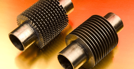
Figure 1: Copper pipes with fins protruding from their exterior to improve heat transfer properties.
Photo is courtesy of Global Metal Engineering
Figure 1 shows an example of this design principle in the real world. The copper pipes incorporate ‘fins’, cylindrical disks that protrude outwards from the exterior of the pipe, into its design. These fins provide additional surface area for heat transfer to take place between the copper pipe and the surrounding air that the copper pipe is in direct contact with.
This is a strategy used to maximize the rate that heat will transfer between the copper pipe and the air whenever a temperature gradient exists between the two. A similar technique can be used in our system design by incorporating fins throughout the exterior of our power amplifier to maximize the contact surface area between our power amplifier and the surrounding air.
After we incorporate all of these variables into our design and develop a power amplifier with good thermal management properties, we can also look at the design of the heatsink and how it can be used to further improve our system’s thermal management properties. In short, the main purpose of a heatsink is to bring our system into direct contact with high velocity air flow to help maximize the rate at which heat will transfer from our system to the surrounding air.
All of the variables that we already discussed should be used similarly in the design of the heatsink. It should be made from highly conductive material, incorporate fins to provide a high contact surface area between itself and any surrounding, colder, conductive mediums present, and provide as much airflow across our system as possible. If all of these variables are incorporated into the design of our system, we can continue to push the limits of what is possible for small, high powered, power amplifier products.
View our full line of COTS Power Amplifiers and Bidirectional Amplifiers that meet specific size, weight, and power consumption (SWaP) requirements to help maximize RF capability and readiness. You can also contact us to learn more about how are extensive RF Design experience can help with your current needs.


Comments are closed